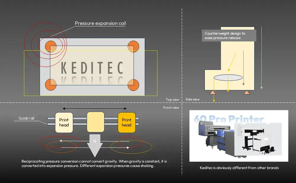
Insufficient base stability is a common issue in entry-level DTF printers. To reduce manufacturing costs, some manufacturers use thin steel plate bases formed by bending, without reinforcing ribs or shock-absorbing chambers. This results in inadequate rigidity.
Print stability is a critical factor in Direct-to-Film (DTF) printing. Shaking or vibration during operation can compromise print accuracy, leading to blurred patterns, misregistration, and reduced production efficiency. This guide provides a comprehensive technical analysis of the root causes of DTF printer shaking and offers practical solutions based on mechanical design principles and industry best practices.
I. Root Causes of DTF Printer Shaking: Base and Counterweight Design
Shaking during high-speed DTF printing is primarily a manifestation of dynamic balance failure in the printer’s mechanical system. The core causes are concentrated in two design aspects: the base structure and the counterweight system.
Base Structure Stability
When the print head moves back and forth at speeds of 0.5–1.2 meters per second, the inertial forces generated cause the base to resonate. For printers with a printing width exceeding 60 cm, the resonance frequency can reach 5–8 Hz, creating coupled vibration with the supporting surface and amplifying the shaking amplitude.
Additionally, poorly designed base-to-ground contact—such as single-point support or small-area contact—fails to effectively distribute the machine’s weight. This intensifies vibration transmission and ultimately leads to positioning deviations in the PET film during printing.
Counterweight System Design
The presence and balance of a counterweight system distinguish mid-to-high-end DTF printers from entry-level models. The print head assembly (including nozzles and ink stack) typically weighs 3–8 kg, generating significant inertial torque during high-speed movement that must be offset by a counterweight system.
If a DTF printer lacks a counterweight device, or if the counterweight block is insufficient in mass or improperly positioned, the machine’s center of gravity shifts continuously with print head movement, resulting in periodic shaking.
Experimental data indicates that when the counterweight mass is less than 1.5 times the mass of the print head assembly, shaking amplitude exceeds 0.5 mm—sufficient to cause blurred patterns or misregistration.
II. Frame and Counterweight Configurations: Cost vs. Performance
The choice of frame construction and counterweight design directly determines both cost and stability performance. DTF printers on the market generally fall into three categories:
Entry-Level: Thin-Walled Steel Pipe Welding + No Counterweight
- Frame: Welded ordinary steel pipe, 1.2–1.5 mm thickness
- Counterweight: None
- Target Users: Individual entrepreneurs, small-batch printing
- Capability: Suitable for desktop printers with print widths under 30 cm
- Limitations: Basic stability only; not suitable for higher speeds or larger formats
Mid-Range: Thick-Walled Steel Pipe Welding + Adjustable Counterweight
- Frame: Welded seamless steel pipe, 2.0–3.0 mm thickness
- Counterweight: Bolt-secured combined plates, 5–8 kg total, adjustable
- Target Users: Small to medium studios
- Capability: Supports print widths up to 40 cm at moderate speeds
- Advantages: Balance between stability and flexibility; counterweight can be adjusted for different print head weights
- Quality Assurance: Frame processing requires flaw detection
High-End: Integral Square Steel Welding + Integrated Counterweight Chassis
- Frame: Welded integral 40×60 mm square steel
- Counterweight: Cast iron chassis integrated with base, 15–30 kg, includes shock-absorbing chamber
- Target Users: Industrial applications, garment factories
- Capability: Supports print widths up to 120 cm at high speeds
- Advantages: Shaking amplitude controlled within 0.1 mm through coordinated shock absorption and center-of-gravity optimization
- Precision: Frame processing accuracy of ±0.5 mm
III. Scientific Counterweight Calculation Methods
Proper counterweight calculation is essential for solving shaking issues. The industry employs three primary methods depending on printer class and application.
Static Balance Method: Suitable for Small DTF Printers
This method focuses on static center-of-gravity balance.
Formula: Counterweight Mass = Print Head Mass × Maximum Print Head Travel Distance ÷ Distance from Counterweight Center of Gravity to Rotation Axis
Example:
- Print head mass: 5 kg
- Maximum travel distance: 60 cm
- Counterweight center-of-gravity distance: 30 cm
- Required counterweight: 5 × 60 ÷ 30 = 10 kg
Application: Simple calculation; suitable for small, bracket-free DTF printers operating below 0.5 m/s.
Inertial Torque Balance Method: Suitable for Desktop DTF Printers
This method accounts for dynamic forces during high-speed operation.
Formula: Counterweight Moment of Inertia = Print Head Moment of Inertia × Safety Factor (k)
Where Moment of Inertia (J) = m × r² (m = mass, r = radius of center of gravity), and safety factor k is typically 1.2–1.5.
Example (40 cm width desktop printer):
- Print head moment of inertia: 0.8 kg·m²
- Safety factor k = 1.4
- Required counterweight moment of inertia: 1.12 kg·m²
- With counterweight radius of 0.2 m, required mass: 28 kg
Application: Standard for desktop DTF printers with external brackets; ensures stability at printing speeds of 0.5–0.8 m/s.
Resonance Suppression Method: Suitable for Production-Grade DTF Printers
This advanced method incorporates vibration frequency parameters.
Formula: Counterweight Mass = Total Equipment Mass × (Resonance Frequency)² × Shock Absorption Coefficient (c)
Where c ranges from 0.3 to 0.8 depending on base shock absorption structure.
Example (120 cm width production-grade printer):
- Total mass: 300 kg
- Resonance frequency: 6 Hz
- Spring shock absorption structure (c = 0.5)
- Counterweight mass controlled at 30–50% of equipment mass
Application: Ensures stability at high printing speeds of 1.0–1.2 m/s through segmented counterweight and elastic buffer design.
IV. Hierarchical Stability Solutions by Printer Width
The industry has established clear stability schemes based on printer width and application scenarios.
Small DTF Printer (≤30 cm Width)
| Characteristic | Specification |
|---|---|
| Typical Use | Personalized small-batch printing |
| Print Speed | < 0.4 m/s |
| Print Head Mass | 2–3 kg |
| Stability Solution | Bracket-free; add 2–4 kg fixed counterweight blocks at base; anti-slip rubber feet |
Desktop DTF Printer (30–40 cm Width)
| Characteristic | Specification |
|---|---|
| Typical Use | Small to medium studio production |
| Print Speed | 0.5–0.8 m/s |
| Stability Solution | External angle steel bracket with 4 adjustable support feet; counterweight installed opposite print head movement direction |
| Expected Shaking Amplitude | 0.2–0.3 mm |
| Additional Cost (Bracket + Counterweight) | $70–110 USD |
Production-Grade DTF Printer (60–120 cm Width)
| Characteristic | Specification |
|---|---|
| Typical Use | Industrial, garment factory production |
| Print Speed | 1.0–1.2 m/s |
| Stability Solution | Integrated counterweight chassis; 15–30 kg cast iron blocks distributed symmetrically; optional shock-absorbing chambers with spring-connected opposing counterweights |
| Expected Shaking Amplitude | < 0.1 mm |
| Counterweight Proportion | Up to 40% of total equipment weight |
V. Quantitative Relationship: Print Head Speed and Shaking Amplitude
The relationship between print head speed and shaking amplitude is nonlinear and positive. Understanding this relationship enables users to optimize parameters for better print quality.
Key Variables
| Variable | Description |
|---|---|
| v | Print head movement speed (m/s) |
| m | Print head mass (kg) |
| M | Total printer mass (kg) |
| k | Base rigidity coefficient (N/m) |
| A | Shaking amplitude (mm) |
Mathematical Model
When the print head moves in reciprocating linear motion at speed v, the inertial force generated is F = m × a (where a is acceleration). During uniform speed phases, inertial force primarily comes from directional change impacts. According to mechanical vibration theory:
A = (k₁ × v² × m) / (k × M)
Where k₁ is a correction coefficient (0.05–0.12), related to mechanical clearance and lubrication.
Practical Verification (40 cm Width Desktop Printer Example)
Parameters: m = 5 kg, M = 80 kg, k = 20,000 N/m, k₁ = 0.08
| Speed (v) | Calculation | Shaking Amplitude (A) |
|---|---|---|
| 0.5 m/s | (0.08 × 0.25 × 5) / (20,000 × 80) | 0.0625 mm |
| 0.8 m/s | (0.08 × 0.64 × 5) / (20,000 × 80) | 0.16 mm |
| 1.0 m/s | (0.08 × 1 × 5) / (20,000 × 80) | 0.25 mm |
Key Insight: Increasing speed from 0.5 m/s to 1.0 m/s results in a fourfold increase in shaking amplitude. This explains why production-grade printers require heavy counterweights. Additionally, increasing total printer mass (M) significantly reduces shaking amplitude—confirming the value of robust counterweight design.
VI. Case Study: Counterweight Optimization in 60 cm Width DTF Printers
The following case study illustrates effective counterweight design principles applied to a 60 cm width production-grade DTF printer.
Integrated Counterweight Chassis
| Feature | Specification |
|---|---|
| Total Printer Weight | 320 kg |
| Counterweight Chassis Proportion | 35% (approx. 112 kg) |
| Chassis Material | High-density cast iron, one-piece casting |
| Support Feet | 6 evenly distributed feet |
| Center of Gravity Height | Below 50 cm (20% lower than conventional designs) |
| Base Rigidity Coefficient | > 35,000 N/m |
Benefit: Low center of gravity improves anti-torque stability; reinforced structure reduces shaking risk.
Dynamic Balance System
| Feature | Specification |
|---|---|
| Print Head Mass | 7 kg |
| Counterweight Configuration | 4 sets of adjustable counterweight blocks on both sides of movement track |
| Counterweight Mass per Set | 5 kg |
| Position Adjustment | Fine-tunable based on printing speed (0.6–1.0 m/s) |
| Shaking Amplitude at 1.0 m/s | < 0.12 mm |
| Performance Improvement | 65% reduction compared to non-counterweight equivalents |
Shock Absorption and Transmission Optimization
| Feature | Specification |
|---|---|
| Chassis-Body Connection | Rubber buffer pads (absorbs 30% of vibration energy) |
| Transport Mechanism | Suction-type rolling transport shaft |
| Positioning Deviation (8-hour continuous high-speed operation) | < 0.2 mm |
Result: Consistent print accuracy maintained throughout extended production runs, meeting the precision requirements of garment printing applications.
Conclusion
DTF printer shaking is fundamentally a systemic issue involving mechanical structure and dynamic balance. Effective solutions must address three dimensions:
- Base Rigidity: Ensure adequate structural strength through proper materials and reinforcement
- Counterweight Calculation: Apply appropriate calculation methods (static, inertial torque, or resonance suppression) based on printer class
- Hierarchical Selection: Match stability solutions to printer width and application requirements
Selection Guidelines:
| Printer Type | Recommended Solution |
|---|---|
| Small (≤30 cm) | Basic fixed counterweights |
| Desktop (30–40 cm) | External bracket + adjustable counterweight |
| Production (60–120 cm) | Integrated counterweight chassis with shock absorption |
Proper counterweight design not only suppresses shaking but also enhances long-term stability and print accuracy, delivering higher production value for DTF printing operations.
References and Further Reading
The following resources provide authoritative technical information on printer mechanics, vibration analysis, and DTF technology:
- Mechanical Vibration Standards – ISO Technical Committee 108
- Industrial Inkjet Printing Technology – IMI Europe Technical Library
- Printing Equipment Stability Guidelines – Specialty Graphic Imaging Association
- Vibration Analysis Fundamentals – SAE International
- DTF Process Technical Documentation – Sawgrass Technology Resources